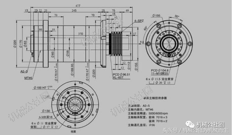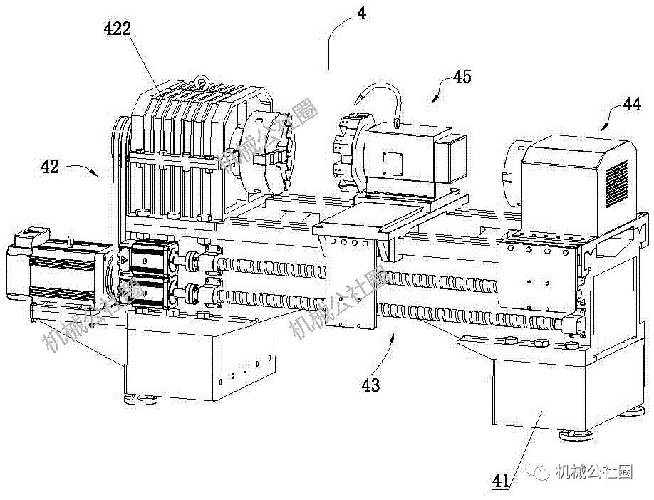
The existing CNC lathe spindle unit is generally equipped with an adjustable double row cylindrical roller bearing and two angular contact ball bearings at the front end thereof, and an adjustable double row cylindrical roller bearing at the rear end of the mechanical commune ring. The spindle unit is suitable for heavy-duty medium speed, with good bearing capacity and rigidity.

However, the adjustment and adjustment of the adjustable double row cylindrical roller bearing is difficult, especially the double row cylindrical roller bearing of the front end is installed in the deep hole cavity of the spindle sleeve, and the mechanical commune circle needs special tools to adjust the nut and repair on the main shaft. The method of grinding the bearing spacer to adjust the clearance of the bearing requires a lot of loading and unloading adjustment to complete, which is very inconvenient.

In addition, in the current common structure, there is an inner sealing sleeve between the right end surface of the main shaft bearing and the step of the main shaft shoulder, and the accumulation error is increased due to the presence of the inner sealing sleeve, and such a spindle unit has low precision.


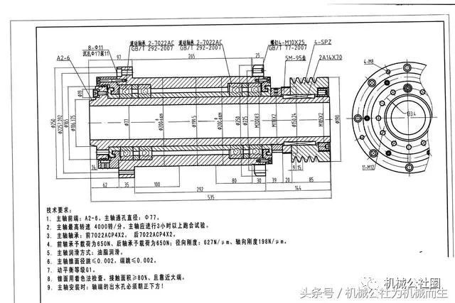
Due to the combined structure of the front double tapered roller bearing and the rear double row cylindrical roller bearing, the spindle unit can withstand relatively large radial and axial forces; the mechanical commune inner sealing sleeve 2 is mounted on the shaft at the front of the spindle. On the outer circumference of the shoulder, a gap of 0.5 mm is left between the inner seal sleeve 2 and the end surface of the tapered roller bearing 2. The left end surface of the shoulder sleeve is in direct contact with the right end surface of the inner ring of the tapered roller bearing, and therefore, the intermediate clamp Compared with the structure of an inner sealing sleeve, the structural precision is high.
 Structural design of spindle unit for low speed and heavy duty CNC lathe

In the figure, 1 is a sleeve, 2 is a pulley, 3 is a nut, 4 is a flat key, 5 is a timing pulley, 6 is an outer sealing sleeve, 7 is a lock nut, 8 is an inner sealing sleeve, 9 is a double Column cylindrical roller bearings, 10 is the spacer sleeve, 11 is the main shaft, 12 is the tapered roller bearing one, 13 is the outer spacer sleeve, 14 is the inner spacer sleeve, 15 is the tapered roller bearing 2, and 16 is the inner sealing sleeve 2. 17 outer sealing sleeve 2, 18 is the sealing ring, 19 is the screw one, 20 is the water outlet hole, 21 is the air outlet hole, 22 is the screw 2, and 23 is the shoulder.
Sleeve 1, nut 3 The pulley 2 and the timing pulley 5 are axially locked and fixed on the main shaft by the flat key 4, the tapered roller bearing 12, the tapered roller bearing 2, the outer spacer 13, and the inner spacer 14 The front bearing assembly, the front bearing assembly, the double row cylindrical roller bearing 9, the spacer 10 are mounted on the main shaft 11, and the spindle assembly consisting of the front bearing assembly, the double row cylindrical roller bearing 9, and the spacer 10 is mounted on In the inner hole of the sleeve 1; an inner sealing sleeve 26 is arranged on the shoulder 23 at the front of the main shaft 11, and a gap of 0.5 mm is left between the inner sealing sleeve 26 and the end surface of the tapered roller bearing 2 15, the mechanical commune The outer end face of the tapered roller bearing 2 15 is provided with an outer sealing sleeve 217, and the outer sealing sleeve 217 presses the front bearing assembly into the inner hole of the sleeve 1 by means of a screw 19; at the right end face of the main shaft 11 A sealing ring 18 is arranged between the outer sealing sleeves 2, 17 and the inner sealing sleeves 2 and 16 form a labyrinth seal of the front end of the main shaft; the inner casing 11 is further provided with an inner sealing sleeve 8 and the right end surface thereof abuts On the left end of the inner ring of the double row cylindrical roller bearing 9, the lock nut 7 will seal the inner seal one, the machine The inner ring of the double row cylindrical roller bearing 9 of the commune circle is pressed against the main shaft 11 together with the front bearing assembly; the outer sealing sleeve 6 is pressed against the outer ring of the double row cylindrical roller bearing 9 by the screw 22 The left end of the sleeve 1 is in the inner hole. The inner sealing sleeve 8 and the outer sealing sleeve 6 form a labyrinth seal at the rear end of the spindle.

An air outlet 21 is provided in the sleeve 1. A water outlet hole 20 is provided at the front end of the spindle.
1. Using advanced technology, the appearance is beautiful and elegant.
2. High structural rigidity, smooth operation and low noise.
3. Equipped with advanced concentration pretreatment equipment (good for sludge flocculation) and low operating cost.
4. The gravity dewatering area is equipped with advanced distributors to distribute materials evenly and extend the life of the filter belt.
5. It has an extra-long gravity dewatering zone and a wedge-shaped dewatering zone, which fully dehydrates the material and ensures that the material will not overflow in the pressing zone.
6. The roller system is arranged scientifically and orderly. Gravity dehydration, wedge dehydration and press dehydration are discharged separately without interfering with each other. The diameter ratio of the press dehydration roller is large and the dehydration effect is good. Therefore, it has large production capacity, energy saving and high efficiency.
7. The continuous operation from feeding to mud cake discharge has a high degree of automation. A PLC interface can be set up as needed to facilitate centralized microcomputer control.
8. The power transmission mechanism adopts mechanical or variable frequency stepless speed regulation, with a large speed regulation range and wide adaptability.
9. The filter belt is equipped with a reliable backwash device to ensure the dehydration effect of the filter belt.
10. Use pneumatic tensioning and pneumatic automatic deviation correction devices to ensure the safe and normal operation of the filter belt.
11. The operation is safe and reliable, using infrared safety protection and a full range of emergency safety parking devices.
12. Filter belts with different structures can be configured according to different materials to achieve high filtration accuracy.
Filter Press,Pp Plate Filter Press,Syrup Filter Press,Belt Filter Press
Changzhou Senjie Environmental Protection Equipment Co., Ltd. , https://www.jssenjie.com