1 working principle of labyrinth seal, sealing mechanism and structure
1.1 The working principle of the labyrinth seal The labyrinth seal is provided with a plurality of annular sealing teeth arranged in sequence around the rotating shaft. A series of intercepting gaps and expansion cavities are formed between the teeth and the teeth, and the sealed medium generates throttling when passing through the gap of the zigzag labyrinth. Effect to achieve the purpose of blocking.
1.2 The application of the labyrinth seal is widely used in steam turbines because of the gap between the rotor and the casing of the labyrinth seal, no solid contact, no lubrication, and thermal expansion, suitable for high temperature, high pressure, high speed frequency. Gas turbine, compressor, blower shaft end and interstage seal, other dynamic seal front seal.
1.3 Seal mechanism of labyrinth seal The function of fluid to generate resistance through the labyrinth and reduce its flow rate is called “maze effectâ€. It has hydrodynamic effects on liquid, including wear resistance effect, flow contraction effect; thermodynamic effect on gas, That is, the heat conversion of the gas in the labyrinth due to compression or expansion; in addition, there is a "breathing effect" and the like. The maze effect is a comprehensive reaction of these effects, so the labyrinth sealing mechanism is very complicated.
1.4 Structure of Labyrinth Seal The structure of the labyrinth seal is that the compressor uses a straight-through labyrinth seal.
2The characteristics of the straight-through labyrinth Because the groove on the shaft surface or the teeth of various shapes are easier to machine than in the hole, the hole is often processed into a smooth surface, and the grooved or toothed shaft forms a labyrinth. This is the straight-through type. The labyrinth is the most widely used straight-through maze because of its ease of production. However, the through-type labyrinth has a gas permeable phenomenon, and the leakage amount is larger than the leakage amount of the ideal labyrinth.
3 Design and selection of localized labyrinth seals 3.1 Leakage calculation of ideal maze The calculation of the leakage of the ideal maze gives the following conditions: (1) The leaking gas is an ideal gas, regardless of the Joule-Thomson effect, ie the gasç„“ only related to temperature; (2)
Suppose the labyrinth is a series of continuous multi-slots, the expansion chamber between the two slits is large enough; (3) adiabatic cyclic expansion through the flow of the slit, where a flow coefficient α is cited; (4) through the seam The flow velocity energy after the mouth is completely restored by the isothermal pressure in the expansion chamber, so the velocity before each slit is asymptotically zero, that is, no gas permeability occurs.
3.2 Labyrinth Gas Seals In addition to special cases, general turbines, gas turbines and other impeller machines use labyrinth gas seals. The radial clearance should be selected according to the following factors: bearing clearance, manufacturing tolerances and assembly errors, component deformation (such as casting shrinkage and out of round), rotor deflection, and amplitude through critical rotational frequency, thermal expansion and resulting Deformation, etc. In many cases, the effects of thermal expansion are most pronounced. Therefore, changes in the size of individual components during start-up and parking, as well as relative displacement of the components, must be estimated in advance. Static and dynamic finite element methods can be used to derive the thermal expansion law with time. The compressor shaft seal clearance requirement of the unit is 0.1~0.13mm. 3.3 Note on the labyrinth seal design The experience accumulated in the labyrinth seal design is summarized. The following points are summarized: (1) Try to convert the kinetic energy of the airflow into heat energy instead of Move the residual speed to the next gap. Keep the proper distance between the teeth and the teeth, or use high-low teeth to force the direction of the airflow. The tooth spacing is generally 5 to 9 mm. (2) The sealing teeth should be as thin as possible and have an acute angle. The thickness of the tip should be less than 0.5mm. When the shaft is occasionally touched by the shaft during operation, the tip of the tooth will wear and disengage first, and the accident will not be caused by local overheating of the shaft due to friction.
(3) Due to the large amount of leaks in the labyrinth seal, care should be taken to prevent contamination of the environment when sealing flammable, explosive or toxic gases. An inflatable labyrinth seal is used, and an inert gas is introduced into the gap, and the pressure is slightly larger than the pressure of the gas to be sealed; if the medium is not allowed to be mixed with air, an aerated labyrinth seal can be used.
3.4 Performance of sealing materials The performance of sealing materials is an important factor to ensure effective sealing. The choice of sealing materials is mainly based on the working environment of the sealing components, such as the use temperature, working pressure, working medium and movement mode. The basic requirements for sealing materials are as follows: (1) have certain mechanical properties, such as tensile strength, elongation, etc.; (2) appropriate elasticity and hardness, small compression set; (3) high temperature and low temperature, high temperature Does not decompose, soften, does not harden at low temperature; (4) adapts to the working medium, does not produce swelling, decomposition, hardening, etc.; (5) good oxygen and aging resistance, durable; (6) wear resistance, Does not corrode metal; (7) easy to shape and process, and the price is low.
3.5 Basic requirements for seal design and selection The leakage of mechanical equipment involves the design, production, use of the seals and the various parts of the mechanical structure, such as the design structure of the mating parts, product processing, assembly quality, etc., so it is necessary to use system analysis. A comprehensive analysis of the points of view to identify the various factors that influence the seal. The basic requirements for seal design or selection are: (1) good sealing performance in a certain pressure and temperature range; (2) low frictional resistance with sealing mating surface, stable friction coefficient; (3) low wear and wear After a certain degree of automatic compensation, long service life; (4) compatible with environmental media and working media; (5) simple structure, convenient disassembly and assembly, low price.
3.6 Common structural measures for seal design
(1) Pressure equalization: equalize the pressure difference between the inner and outer sides of the sealing part. If an appropriate ventilation window is provided, a small pumping element is added in the medium passage to make the contact pressure distribution of the seal uniform.
(2) Grooming: Open the oil return groove, hole, and oil deflector on the parts to drain the leaked fluid back to the oil pool.
(3) Increase the flow resistance: such as lengthening the leakage passage or the flow path to increase the oil flow. The ATLAS centrifugal compressor labyrinth seal has large localization and transformation, fast braking speed, full-section catching, etc., which can ensure the safety of the strong belt. Operation, to ensure the safe production of mines, has a good promotion value.
(4) Plugging: Sealing the interface leakage channel by sealing technology, for example, using a sealing member, applying a sealant, sealing the sealing tape, or welding the surface of the non-moving joint, riveting, pressing, folding Wait for the leak channel to be blocked.
(5) Liquid film barrier: The method of improving the precision and control gap between the dynamic sealing surface of the equipment to maintain a proper lubricating film to prevent or reduce leakage and lubricate the surface.
(6) Reflow throwing: use reflow structure to seal, or add reflow measures such as spiral grooves on the parts and use the oil slinger, oil sump, etc. to throw the leaked oil back into the oil pool.
(7) Vibration and corrosion protection: eliminate vibration and impact of the sealing part; prevent corrosion.
(8) Use lubrication such as grease or solid lubricant.
3.7 Correct selection of the material and variety basis of the seal
(1) Working conditions: such as pressure, speed, temperature, limit of leakage rate, working life of seals, compatibility with lubricants, environmental media (air temperature, air pressure, presence or absence of dust, etc.), friction conditions, wear Limits, etc.
(2) Requirements for mating parts: such as the geometry of the shaft and the fitting, surface roughness, space size, clearance, eccentricity, movement type, lubrication film condition, etc.
(3) Price requirements and economy: At the same time, the corresponding design of the mating parts should be carried out, such as the groove size and precision of the installation of the seal, the surface roughness, the amount of shaft eccentricity, and the compression ratio of the seal.
(4) Seals are common basic components. The size series, tolerances, materials and mounting groove dimensions and tolerances of most types of products and their design calculation criteria have been standardized. They can be selected according to the corresponding national or industry standards. .
In the localization stage of sealing, we use high-tin babbitt alloy instead of the inner layer of the sealing body. The original composite layer material is German silver. The babbitt alloy can be easily divided into three types: high-tin alloy, high-lead alloy and intermediate alloy ( Both tin and lead in the alloy account for an important proportion). In all of these alloy systems, both bismuth and copper are important alloying and hardening elements, and their structure consists of hard, intermetallic compounds dispersed in a soft matrix.
4 comparison of working conditions before and after sealing localization
In order to fully understand the situation before and after the localization of the shaft seal, the operation data of the same period in May 2005 were reviewed, and the data of the operating conditions in May 2010 were compared.
From the table, the modified process is obviously better than the same period of 2009. In particular, the bearing temperature after the shaft seal has dropped significantly at around 5 °C. It can be said that the transformation is very successful.
5 Conclusion
Through the analysis of the shaft seal condition of the imported multi-stage centrifugal compressor used in the production of caprolactam in Baling Petrochemical Co., combined with the inventory status of spare parts in the overhaul stage, the localization of the first, second and third stage shaft seals of the compressor unit was carried out by bold practice through domestic practice. Modification, this article from the sealing mechanism, the choice of sealing materials, the gap of the labyrinth gas seal, the basic requirements of the seal design and selection, the necessity and feasibility of sealing localization, the comparison of the process status, the feasibility and necessity of implementing the localization reform Sex. Science must have practical experiments to prove that the localization of the seal, we just took the first step, to take the equipment management and maintenance technology to the next level, but also need serious work attitude and effective process control.
Fitness Rope
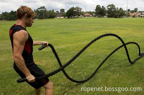
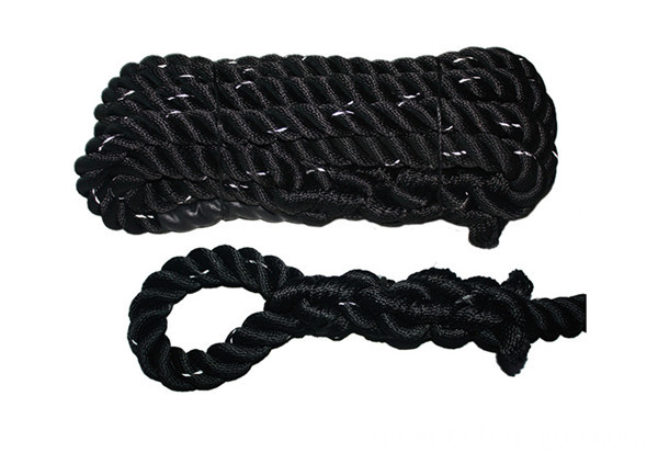
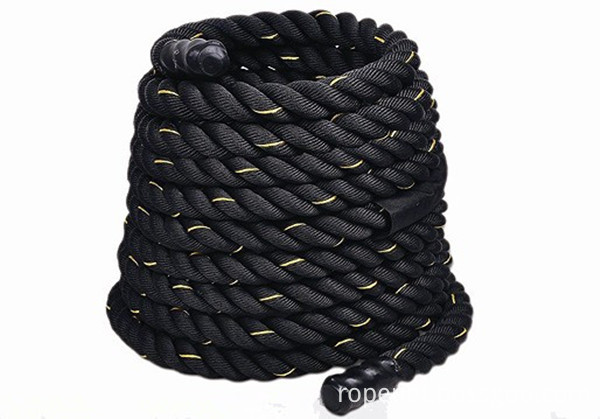
The training rope (Battle Rope, Gym Rope, Crossfit Rope) are made of twisted anti-corrosion, wear-resistant, soft, gravity vertical fibers, therefore the rope are durable, not easy to lose, looks smooth and not easy to stick dust. User will feel smooth when hold it, and user are able to complete all kinds of wave action. This training rope are heavy enough, is one preferred choice for a professional fitness user.
Description of Fitness Rope
Name: Fitness Power Battle Triceps Physical Training Fitness Pull Rope for exercises / Battle Rope / Training Rope
[Product Material]
1, Polyester Fiber (Anti-corrosion, Wear-resistant, Anti-aging, Compliant, Gravity vertical).
2, Polydacron Combination Fiber ( Anti-corrosion, Wear-resistant, Anti-aging, Gravity vertical ).
[Product Color]Black, Black with Yellow
[Specification]25 mm (Polyester 450 g/m)
38 mm (polyester 690 g/m, Polydacron 640 g/m)
50 mm (polyester 1480 g/m, Polydacron 1480 g/m)
SPECIFICATION
[Battle Rope 1](TNXL001)
[Training Way]Swing, Shaking, Screw Turn
[Specification]38 mm / 50 mm
[Length]5m / 10m / 15m


If you need more info about Fitness rope / Battle Rope / Training Rope, pls kindly send email to us directly.
Fitness Rope,Training Rope,Gym Rope,Rhythmic Gymnastics Rope
ROPENET GROUP CO.,LTD , https://www.cnparacord.com