0 Introduction The measurement of the Young's modulus of metal materials is one of the necessary experiments in physics experiments in universities and engineering colleges. The key to the measurement of the Young's modulus of elasticity of a wire lies in the accurate measurement of the tiny length of the wire. Some laboratories in the country still use the optical lever method to measure the tiny length of the wire, and this measurement method is The adjustment of the optical path has strict requirements, which are difficult to measure and difficult to grasp, the operation is relatively tedious, and the reading process is error-prone and takes a long time. In response to the development status and development requirements of domestic university physics experiments, the use of high technology to continuously improve physical experimental equipment and to achieve automatic detection and control of experimental equipment has become a major trend. Therefore, we need to open up new measurement methods to improve experimental instruments.
1 Systematic overall design We first use the device that measures the Young's modulus to produce the tiny displacement, then uses the even beam to shine on the silicon photoelectricity battery, uses the baffle connected to the metal wire to place the light between the light source and the silicon photoelectricity battery, like chart As shown in Fig. 1, when the baffle is moved, the output current changes, and because the baffle light changes much, the output current has a corresponding amount of change (linear change), and then the electric signal is amplified and converted into a single-chip microcomputer. Since the program written in advance has been input into the SCM, real-time automatic measurement, data processing and display can be realized by the SCM, thereby achieving automation and high precision of Young's modulus measurement. After the operator only needs to be familiar with the operating instructions, he or she can use the keys on the keyboard to achieve the experimental requirements. The final result can be displayed on the LED display connected to the microcontroller.

2 hardware part The hardware part mainly has the following modules: photoelectric conversion module composed of light source and silicon photocell; current-voltage conversion and amplification and filtering module composed of TL084 chip and its peripheral components; AD conversion module; The data processing and output module consisting of a microcontroller and an LCD are shown in Figure 2. The following two modules are briefly described below.

One-time fit: r=-0.04433x+86.4396
Quadratic fit: r=2.323e-005x^2-0.048232x+86.5482
Third-order fit: r=-3.2246e-007x^3+0.00010449x^2-0.053677x+86.6233
From the above equation, we can see that as the number of fittings increases, the order of the coefficients of the higher order terms becomes smaller and smaller, and the range of change is large. Considering the experimental feasibility and accuracy requirements, the relationship of rx can be handled once. Therefore, we can use the silicon photocell to change the displacement of the light block to the change of current to measure. The physical map is shown in Figure 1.
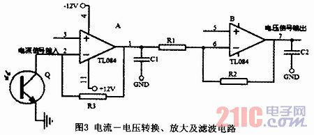
2.2 Current-voltage conversion and its amplification, filtering The most critical part of the hardware module is the processing of the silicon photocell converted current signal. Since analog-to-digital conversion is necessary, the current signal must be converted into a voltage signal. Since the signal obtained by the conversion is small and contains a noise signal, we need to amplify and filter it. Here, the TL084 integrated amplifier is used for current-voltage conversion and amplification. The RC circuit is used for filtering. The circuit diagram is shown in Figure 3. The converted voltage signal is directly input to the input of the AD conversion circuit, and the AD-converted output signal is then sent to the microcontroller for processing and display. Which AD conversion uses a 12-bit converter AD574.

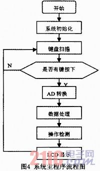
3 software part In order to facilitate program debugging and improve reliability, the program design uses a top-down, modular, structured programming approach. The program divided by task module mainly includes initialization program, main program, A/D conversion subroutine, data processing subroutine (including zero adjustment, judgment operation error, displacement value and Young's modulus value), LCD display. Programs, keyboard scan subroutines. The main flow chart of the system is shown in Fig. 4. The operation detection is to help remind the operator. If there is no mistake, the LCD display will show the corresponding data value of the function key. If the operation is wrong, the LCD display will show the word EOF.


Where L = 100.00 cm, m = 3000 g, and g = 979.4 cm/s2. uF only takes a valid number and writes the result expression from the "last alignment" principle:
E=E±uE=(1.8±0.3)×1011(N/m2)
5 Conclusion This method can greatly simplify the original experimental device, improve the efficiency and accuracy of the experiment, and the cost is lower than the original. After the improvement, it not only retains the teaching content of the original experiment, but also helps students understand the structure, principle, characteristics, and usage methods of the photoelectric sensor, applies advanced scientific and technological achievements to the teaching experiment, and expands the students’ knowledge. The instrument will also be an example of the modernization of classic experimental teaching.
At our factory outlet, we offer a wide range of hot-selling graphite moulds for casting. These moulds are manufactured using high-quality graphite materials, ensuring durability and long-lasting performance. Our graphite moulds are designed to withstand high temperatures and provide excellent dimensional accuracy for producing high-quality castings.
Some of our popular graphite moulds for casting include:
1. Graphite Ingot Moulds: These moulds are used for casting metal ingots, such as gold, silver, and other precious metals. They come in various sizes and shapes to accommodate different casting requirements.
2. Graphite Crucibles: Crucibles are essential for melting and pouring molten metal into moulds. Our graphite crucibles are highly resistant to thermal shock and have excellent heat retention properties.
3. Graphite Dies: Dies are used for casting complex shapes and intricate parts. Our graphite dies are precision-machined to ensure accurate and repeatable casting results.
4. Graphite Plates: Plates are used for casting flat or thin metal parts. Our graphite plates are available in various thicknesses and sizes to meet different casting needs.
5. Graphite Rings: Rings are commonly used for casting cylindrical or round-shaped metal parts. Our graphite rings are highly durable and can withstand high temperatures and pressures.
All our graphite moulds are carefully crafted to meet the highest quality standards. They undergo rigorous quality checks to ensure they are free from defects and can provide consistent and reliable casting results.
If you are looking for high-quality graphite moulds for casting, visit our factory outlet to explore our wide range of hot-selling products. Our knowledgeable staff will assist you in finding the right moulds for your specific casting requirements.
Graphite Mould,Graphite Bar,Graphite Plate Sheets,Graphite Ingot Mould
Yixing Xingfeng Carbide Mould Co.,LTD , https://www.xfcmould.com