1 Development Status at Home and Abroad
In a five-axis machine tool, three moving axes and two rotating axes control the displacement and orientation of the tool relative to the machining surface, respectively. A variety of layouts can be obtained by connecting the five axes in series in different orders. Among them, the layout in which the two rotating shafts are directly connected to each other has special advantages: 1 It accords with the habit of kinematics thinking; 2 Compared with the non-straight structure of two rotating shafts, the rotating shaft changes the knife When the rod space is pointing, the position of the tool tip relative to the workpiece is less offset, which reduces the compensation of the moving axis. 3 The post-processing calculation is simple and generally similar to the radius compensation of the ball-shaped tool. The layout is specifically divided into two types: 1 The two rotary shafts jointly drive the workpiece, that is, the double rotary disk structure; 2 The two rotary shafts jointly drive the tool, and its structure is similar to the mechanical arm. The former's cutter shaft is easy to install and rigid, and is mostly used for machining; while the latter can obtain higher rotational speed, more flexibility, and is mostly used in laser cutting and other fields and is called a guide head.
The typical structure of the guide head is shown in Fig. 1. The rotation axes C and A intersect with the tool axis T at the same point. The light beam passes through 4 times of 90° reflection and exits from the geometric intersection. The axis C and axis A control the tool (or beam) respectively. The horizontal rotation angle and the pitch angle α, whose optical path resembles the character Ω, are tentatively named as Ω structures for the sake of expression.
Figure 2 is a simplified version of the Ω structure, and its application is also very extensive. Because the light path is shortened, the above three axes cannot intersect at one point. The advantage is that the structure is simple and easy to manufacture and install, and the optical path loss is small; the disadvantage is that the post-processing is more complex than the Ω structure. When machining the curved surface, the axis needs to be moved to compensate the eccentricity LCA in the figure. At the same time, the utilization of the travel of the moving shaft is also reduced.

In recent years, NTC (Nisshin Toyama) and Mitsubishi, which are leaders in the field of laser cutting, have adopted a new type of guide head in their five-axis laser processing system (Fig. 3). The axis C is arranged as usual. A rotary axis φ intersects axis C at an angle of 45°, and cutter axis T rotates about axis φ and maintains it at 45°. Its light path resembles a three-character character, tentatively named as a ∑ structure. The structure of germanium is still rare in domestic related fields. Its novel design brings many advantages and is worth learning from.

Figure 3 Beam guide head structure
2 Kinematics characteristics of the crucible structure
As shown in FIGS. 3 and 4 , in the crucible structure, the axis C, the axis φ, and the cutter axis T intersect at one point, and the cutter tip (or laser focus) is precisely positioned at the geometric intersection point during installation. This allows the axis C and the axis φ to rotate arbitrarily, the tool nose position will not be changed, so in the five-axis linkage process, the position accuracy of the machining trajectory depends only on the three movement axis, but with two rotation axis elements.

Compared with the traditional Ω structure, the advantages of the positive structure are mainly reflected in:
1 Since the position control of the three systems is independent of the angle control, its position accuracy is more reliable, which is particularly important for laser cutting and other processing. Because the position accuracy during processing not only determines the trajectory generation, but also relates to the distance between the guide head and the workpiece surface. This directly affects the position of the laser focus and the auxiliary air blowing nozzle, and ultimately affects the cutting quality, including the uniformity of the slit width and the formation of the incision. Sex and dregs on the back. In addition, this is also very beneficial for the installation and commissioning of machine tools.
2 The stroke of each guide rail in the ∑ structure is fully utilized, while the processing range of the moving shaft in the Ω structure is usually smaller than the guide stroke.
For example, consider the Ω guide head machining the semicircle I-II-III-IV of radius R in Fig. 4. The synthetic axis of the moving axis is a semicircle with a radius equal to (R + Lr) (Lr is the length of the tool axis T, Fig. 4 Medium Lr=MII). Therefore, the maximum work piece radius that can be machined is reduced by Lr compared to the vertical structure (for the moment, the Z-axis travel limit is not considered).
3 Traditional Ω-guided heads consume more time and energy for the same machining object compared to the stern structure, and the moving axis is forced to run at a higher speed, for arcs with a very small radius (including full circles ) The processing is particularly unfavorable and the analysis is as follows.
At present, laser cutting usually uses oxygen assist. In order to achieve smooth cuts and reduce dross, the cutting speed is high, usually V≈15mm/s (the corresponding speed of the thin plate is higher). In Fig. 4, let R = lOmm, Lr = 295mm. It can be seen from the geometry that when the Ω guide head processes the semicircle, the linear velocity of the moving axis is:
VΩ=(Lr + R)V/R=450 mm/s
This speed exceeds the limit of the moving axis speed of the general machine tool. When the multi-axis linkage is performed, the speed also imposes severe requirements on the dynamic characteristics of the moving axes. This increases the hardware cost of the machine tool intangibly, and the structure avoids this problem.
The 4-level structure is particularly convenient for teaching programming in machine tools. Teaching programming has gradually become a must-have feature for multi-axis machining machines. It can realize quick processing when there is no part 3D model. When teaching programming, generally only the coordinates of the moving axis are obtained. After the surface reconstruction based on the coordinates of the moving axis, the coordinate of the rotating axis can be obtained.
At any point on the surface, the ∑ system can directly obtain the coordinates of the moving axis, while the Ω structure must perform the inverse of the tool radius compensation. In addition, when teaching, it is necessary to manually set the knife at each point, adjust the position of the tip (or tip of the probe) to just contact with the machining point, and adjust the blade axis as far as possible along the surface normal direction, which is very troublesome to operate. Due to the independent movement of the movement axis and the rotation axis of the cymbal structure, the labor intensity of its teaching work is much lower than that of the zero structure. Tool structure data postposition processing.
From the foregoing analysis, we can see that in the three moving axes, the ∑ structure does not require special post-processing. The CAM software moves the axis data generated based on the 3D model of the part and can be directly used for subsequent processing. The Ω structure needs post processing, that is, The compensation of the tool-shaft length Lr is superimposed on the raw data of each moving axis.
However, in the case of two rotating shafts, the situation is opposite. The crucible structure requires additional compensation for the horizontal corner. This is because when the axis φ changes the pitch angle α of the arbor, it also changes the horizontal angle θ of the arbor at the same time, and the resulting additional horizontal offset is Δc (see Fig. 4). The axis C must perform this offset. make up. The specific analysis is as follows.
In Figure 4, the auxiliary line IIs is parallel to the X axis, and M' and N' are the projections of M and N in the plane of the axis C-axis φ, respectively. Definition C is the angle of rotation of the connecting rod JK with respect to the positive X axis. Defining φ is the rotation angle of the connecting rod PM about its initial position PQ. At point I, φ=O (the optical path at point I has been omitted), and at point W, φ=2n. Define the horizontal angle θ of the normal of the surface as the angle between the horizontal projection (IIN) of the normal vector (IIM) and the X-axis. Defining the elevation angle α of the normal vector of the surface is the angle between the normal vector (IIM) and its horizontal projection (IIN).
Without loss of generality, at point II, it is now known that the normal vector of the surface is IIM, its angular coordinate is (θ, α), and the angular position (c, φ) of axis C and axis φ is required.
From the geometric relationships in the map,

The additional offset generated by the rotation angle φ to the horizontal rotation angle θ is Δc. The following relationship is shown in the figure for △c:

The position of axis C available in the horizontal plane SIIQ is:
C=θ+(-Δc), where

The relationship between φ-α and △c-α is shown in Fig. 5. The φ-α curve is very smooth and has no singularity. The curve is close to the straight line with a slope of 2, which is beneficial to the control of the tool axis vector. . More disadvantageously, the slope of the curve is very large at the initial stage (nearly α=0), where the rotational speed corresponding to the φ axis is high, but this situation is less likely to be encountered in actual machining. The △c-α curve is similar to it.

Figure 5
When the axis C and the axis φ rotate within 2 Л, the motion of the ∑ structure is not decomposed. For example, at point II in Fig. 4, the mirroring of the guide head with respect to the end face of the cylinder can also make the tool axis T match the normal of this point. The specific motion decomposition is customized by the CAM software according to the processing type to improve the processing efficiency. For example, for machining in the horizontal plane (or close to horizontal), the axis C allows rotation in the 2° range, and the axis φ is limited to 0-Л; when processing the section of the extended curved surface shown in FIG. 4 , the axis φ allows 2 turns, On the other hand, the axis C swings in a small range near the direction of the drawing (the axis of the cylinder in FIG. 4).
3 Conclusion
This paper introduces a novel five-axis machining guide head and analyzes the advantages of the structure in combination with practical applications. In the field of laser processing, high-speed sharpness, and coordinate measurement where the cutting force is very small (or zero), the guide head structure can be well applied.
| Measurements (m) | can be customized |
| Certificate |
CE,ASTM,ISO14001, ISO18000, ISO9001 Certificate,
and GS certificate from TUV Company of Germany.
|
| Color | Be customized |
| Materials |
a.Jumping Mat: Imported from United States
b.Foam Pad:EPE, waterproof closed-cell foam, mildew protection, uneasy to lose shape
c.Pad:PVC(500D,500D) fabric
d.Springs:Galvanized steel with good elastic performance
(Different material is available according to your needs)
|
| Advantage |
a.Anti-UV
b.Anti-static
c.Security
d.Environmental protection e.Uneasy to lose shape |
| Function |
1.Can protect children safe when they playing indoor, and let they enjoy the play freely 2.Suitable for improving Children energy and imagination 3.Helping them grow up happily, cleverly, and healthily |
| Installation | Professional CAD instruction, assembly procedure and project case . |
| Age Range | Children and adults |
| Apply to | Amusement park, gymnasium, Kindergarten, Preschool, etc. |
| Packing | Standard export packing |
| Warranty Period | 2 years on mats |
| Remark |
We can design and produce as your requirements |
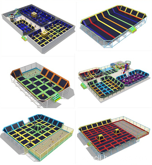
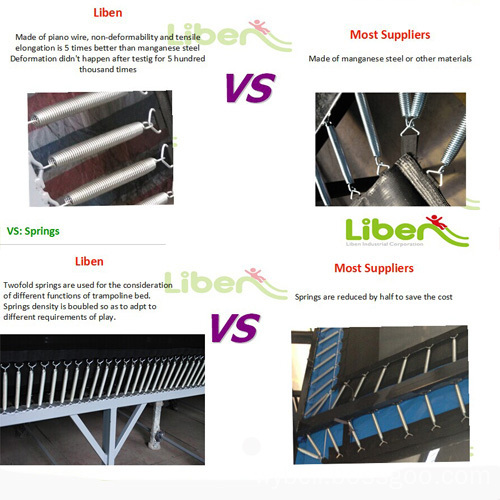
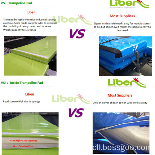
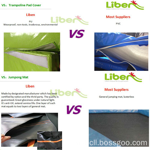
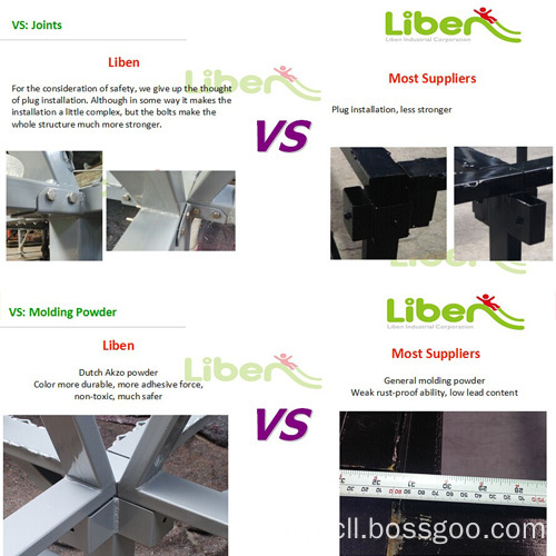


Playground Trampoline Courts, Trampoline For Fitness, Springs Trampoline Park,Commercial Trampoline Park
Liben Group Corporation , https://www.indoortrampoline.de